
Swimming Pool Plumbing Diagrams Inground Pool Kit Plumbing Layouts
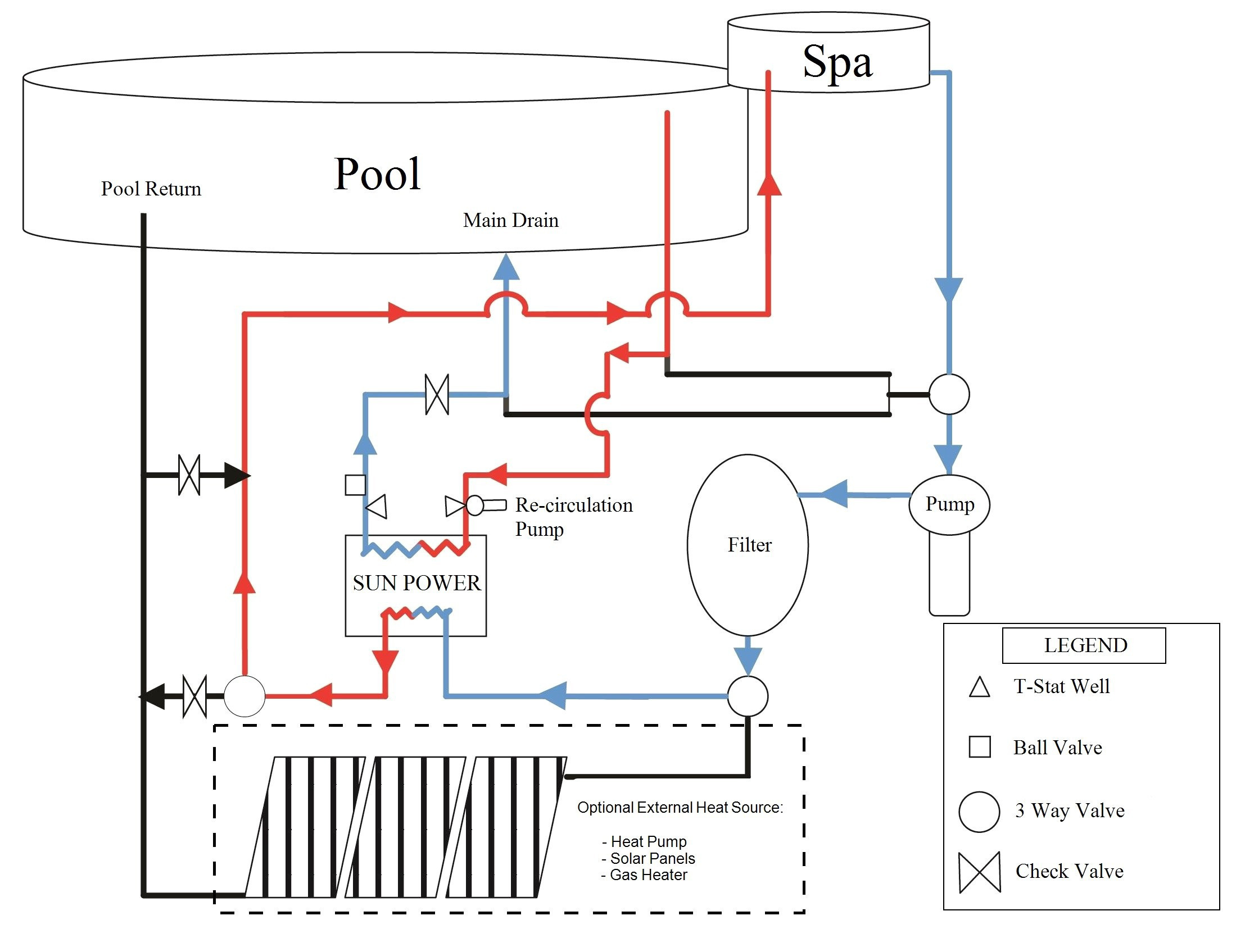
Basic Pool or Spa Only Plumbing Diagram 2 Jandy 3-Way Valves 1 Jandy 2-Way Valve 1 Jandy Check Valve 2 Jandy Valve Actuators Common pool plumbing layout for the pool and spa combo design with booster pump cleaner line, drawing off of pool return line. Solar Pool Plumbing Diagram 5 Jandy 3-Way Valves 1 Jandy 2-Way Valve 1 Jandy Check Valve

Hayward Pool Plumbing Diagram
Keeping every part of your pool plumbing system in mind will help you maintain your clean, sparkling pool, and extend your equipment's longevity.. Swimming Pool Plumbing Diagram.. Hayward SP1419D Hydrostream Return Jet Fitting - 1-1/2 in. MIP Thread - 3/4 in. Opening . Buy Now .
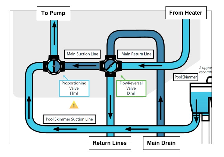
(Solved) Where to Install Pool Check Valve XHVAL
Place AquaGenie in the cutout and mount from the back with (8) #10 x 3/4 hex washer head type AB screws. Cutting Note: The best results will be obtained by using a jigsaw with 8 T.P.I. (fast cut, medium finish) blade. If Jigsaw is not available, use keyhole saw with 8-10 tooth combination blade.
Plumbing Drawing at GetDrawings Free download
Network Hardware Hayward OmniLogic Quick Reference Manual. Wired network setup (2 pages) Lighting Equipment Hayward OmniHub Installation Manual. Pool automation control (61 pages) Lighting Equipment Hayward OnCommand Installation Manual. Automation pool controller (32 pages) Lighting Equipment Hayward OnCommand Operation Manual.

Hayward Salt Cell Plumbing Diagram
Selecting Pump's Discharge Position (4 Steps) Your Hayward Power-Flo Matrix™ pump can be easily positioned for horizontal or vertical water discharge. Step 1: Remove ALL plumbing attached to pump. Remove pump from base (if applicable). Page 8 - B. Disconnect all electrical power service to pump before beginning shaft seal replacement.
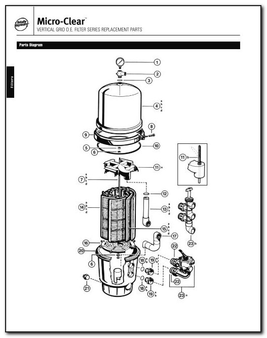
Hayward Pool Filter Assembly Diagram
With any newly installed residential swimming pool, main drains must be installed in accordance with the Virginia Graeme Baker Pool and Spa Safety Act. See our article here for more information on why you need two main drains. ROUTE YOUR PLUMBING. 1 Skimmer, 2 Main Drains, & 2 Returns . 1 Skimmer, 2 Main Drains, & 3 Returns
.png)
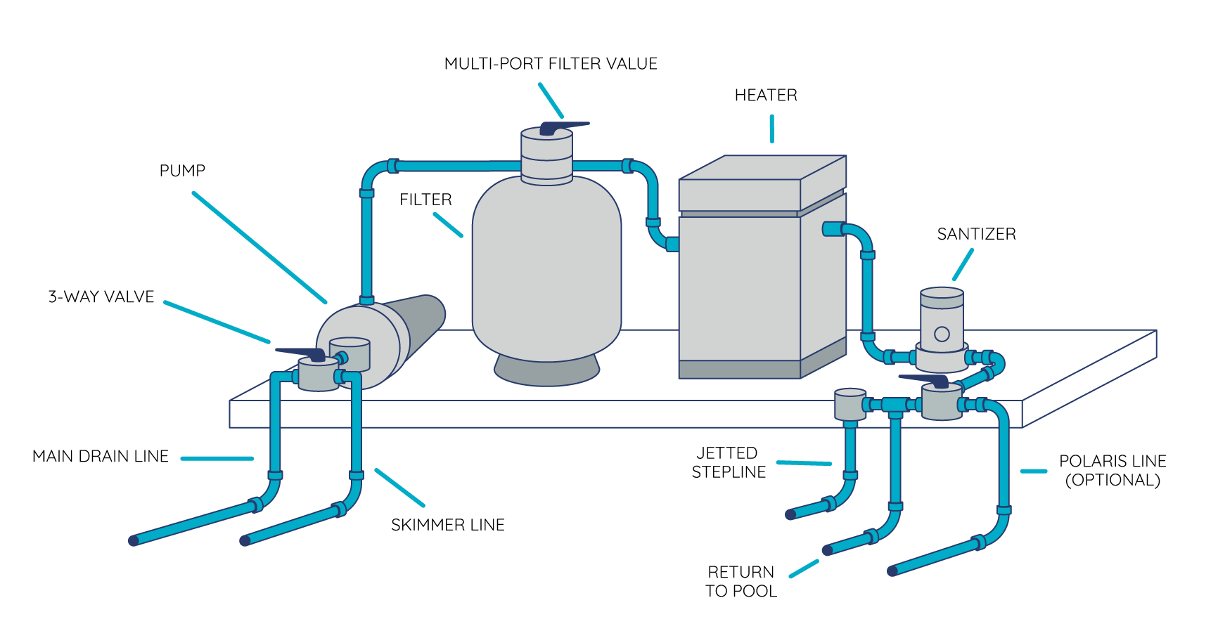
How To Route Your Pool's Plumbing And Set Up Your Equipment Pad
Step 1 Balance the pool water before installing the Aqua Rite Salt Generator. Note: If the pool does not have new water, add one quart of metal remover and one quart of a non-copper based algaecide to the pool. Click Here to Find Your New Aquarite Generator or Replacement Salt Cell Step 2
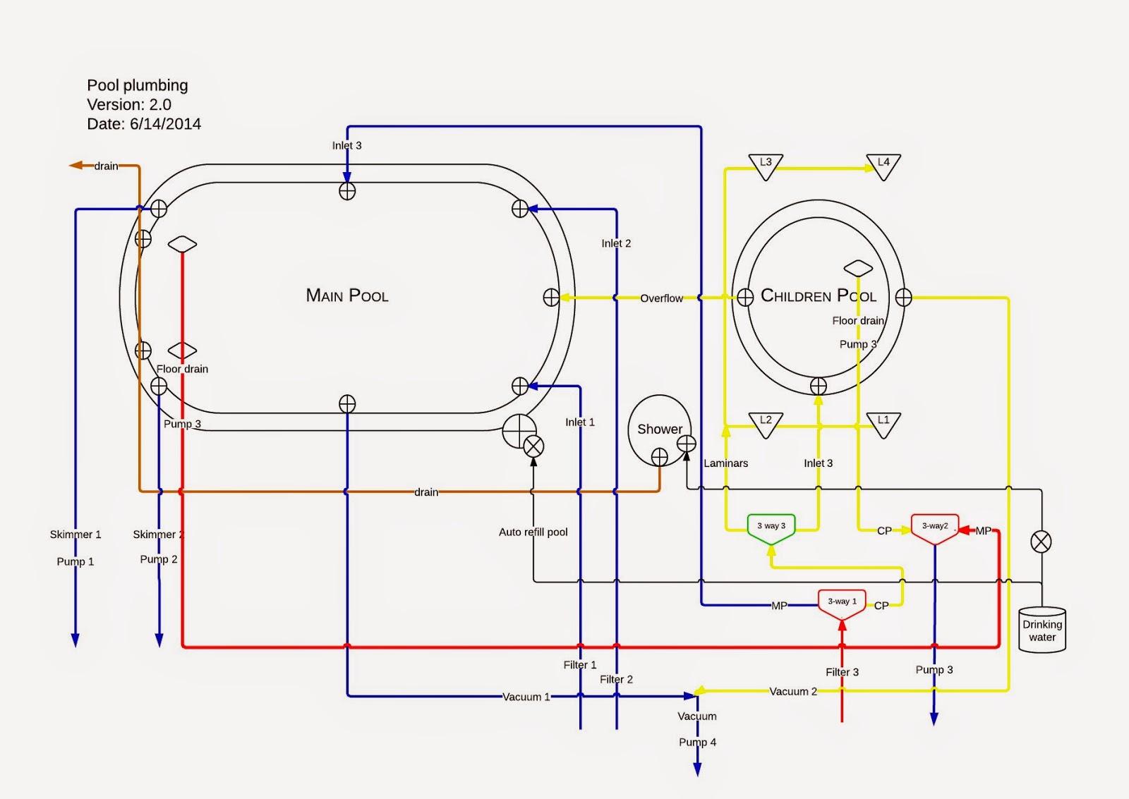
[DIAGRAM] Typical Plumbing Diagram
Hayward Pool Products 620 Division Street, Elizabeth, NJ 07207 Phone: (908) 351.5400 www.haywardnet.com. USE ONLY HAYWARD GENUINE REPLACEMENT PARTS. Connect the pool suction plumbing between the skimmer, pool suction outlet (from the pool) and the pump. 6. Connect the pump discharge (pump OUTLET) to the top port of the filter (filter INLET).

harris pool pump wiring diagram
Welcome to Hayward Pool Products Manuals Hub! Dive into a seamless pool ownership experience with our comprehensive collection of user-friendly manuals. Whether you're a seasoned pool enthusiast or a first-time owner, our manuals provide clear, step-by-step instructions for setting up, maintaining, and troubleshooting your Hayward pool equipment.

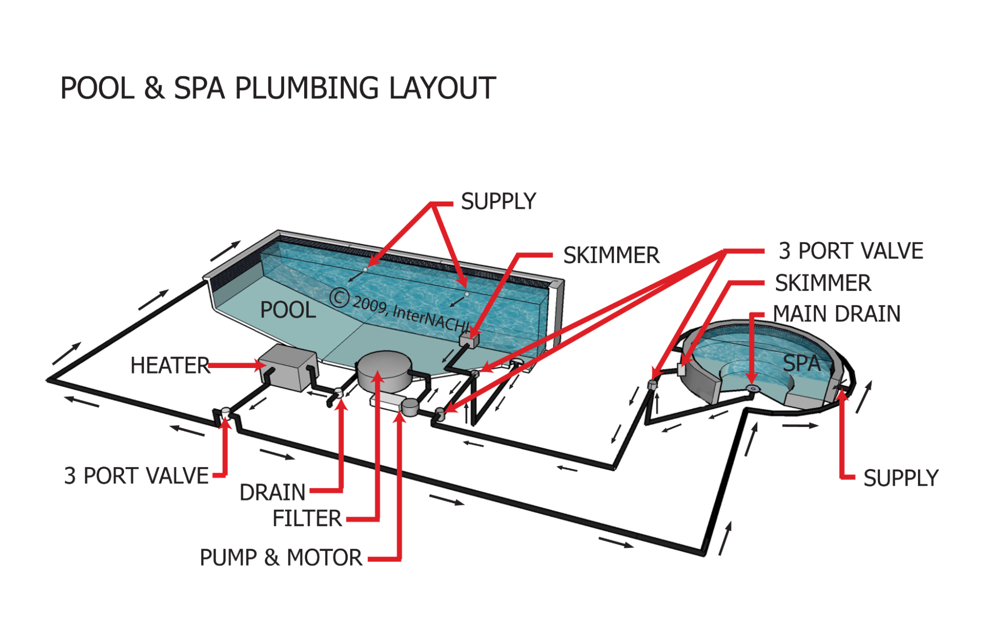
Pool & Spa Plumbing Layout Inspection Gallery InterNACHI®
Hayward Super Pump SP2610X15 Pdf User Manuals. View online or download Hayward Super Pump SP2610X15 Owner's Manual. Plumbing. 6. Fittings. 6. Electrical. 6. Voltage. 7. Grounding and Bonding. 7. Start-Up & Operation. 7. Priming Pump. 8. Maintenance. 8.. Water Pump Swimming Pool Vacuum Lighting Equipment Swimming Pool Filter Water.

Heat Pump Manual
What is a Hayward Pool Pump Diagram? A Hayward pool pump diagram is a visual representation of the internal components and their connections within the pump. It provides a detailed overview of how water flows through the pump and outlines the various valves, switches, and filters involved in the process.
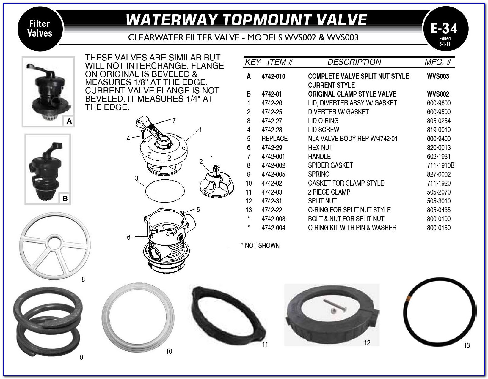
Multiport Valve Pool Filter Diagram
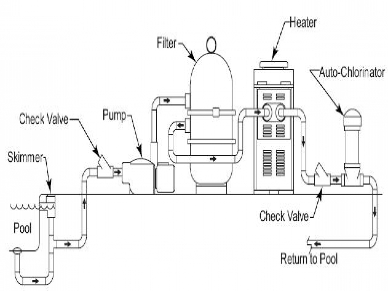
A filtration diagram shows an accurate placement of the pipes in the filtration network and how they're connected. It shows the line and valve connections between the pool and the pool room. You can tell the location of the filter, pH control, disinfection device, valves, and pool heater from an inground pool diagram. Pool Connection Schematic

Pin on Swimming pool plumbing
Inground Pool Skimmer Plumbing Diagrams. December 27, 2019April 20, 2023 Rob Cox. When you look down into your pool skimmer, you may see two holes, one at 12 o'clock and another opposite hole, at 6 o'clock. This gives the pool builder some flexibility in how to connect the plumbing pipes underneath the skimmer.
Inground Pool Drain Diagram Best Drain Photos
All SUMMIT pool heat pumps have a Scroll compressor, an electronic with service analyzer, a titanium heat exchanger tube warranted for 10 against corrosion and a UV-resistant plastic cabinet that eliminates all mainte-nance for life. All components are of superior quality, which presents you with an effective, state-of-the-art technology heat pump.
Hayward Super Pump Wiring Diagram 115v
A multiport valve is usually found on the filter. It allows you to direct water through the filter to either clean the water, rinse or backwash the filter, or expel water to waste, which is helpful when you want to, say, vacuum your pool. Pentair 6-Way Clamp Style Multiport Valve. This is a replacement multiport valve for Pentair sand filters.
(Solved) Where to Install Pool Check Valve XHVAL
May 11, 2013. 6. Aug 19, 2018. #1. We are in the middle of a new build fiberglass pool with 4 Hayward Jet-Air lll Hydrotherapy Fittings. I don't think the installer has installed them correctly. Does anyone have a diagram, photo, or video of what a correct installation should look like?